Meadow.Foundation.Motors.HBridgeMotor
| HBridgeMotor | |
|---|---|
| Status | |
| Source code | GitHub |
| NuGet package |  |
An h-bridge motor controller enables a control signal to drive a much larger load in either polarity, allowing Meadow to drive DC motors in forward or reverse from an external power supply. Using pulse-width-modulation (PWM) as the control signal, provides forward or reverse control, and variable speeds in either direction.
Code Example
protected HBridgeMotor motor1;

public override Task Initialize()
{
    Resolver.Log.Info("Initializing...");

    motor1 = new HBridgeMotor
    (
        a1Port: Device.CreatePwmPort(Device.Pins.D07, new Frequency(100, Frequency.UnitType.Hertz)),
        a2Port: Device.CreatePwmPort(Device.Pins.D08, new Frequency(100, Frequency.UnitType.Hertz)),
        enablePort: Device.CreateDigitalOutputPort(Device.Pins.D09)
    );

    return Task.CompletedTask;
}

public override async Task Run()
{
    Resolver.Log.Info("TestMotor...");

    while (true)
    {
        // Motor Forwards
        motor1.Power = 1f;
        await Task.Delay(1000);

        // Motor Stops
        motor1.Power = 0f;
        await Task.Delay(500);

        // Motor Backwards
        motor1.Power = -1f;
        await Task.Delay(1000);
    }
}
Sample project(s) available on GitHub
Wiring Example
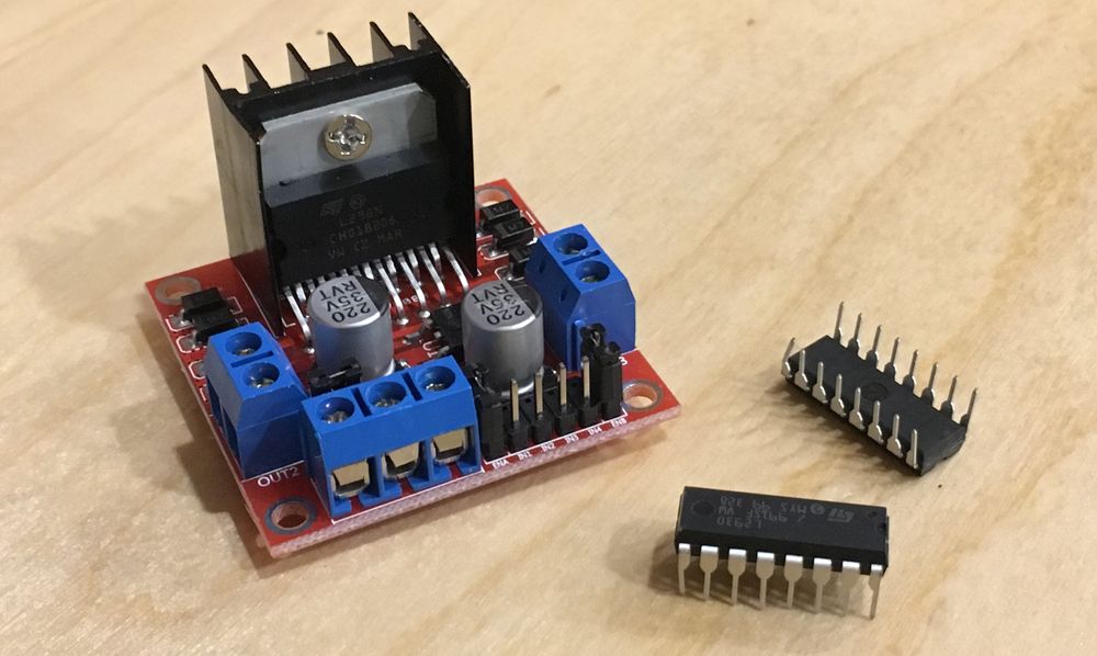
Though h-bridge motor controllers come in various form factors, they typically share the following pins and usages:
| Motor Controller Pin | Description |
|---|---|
| 1,2EN or ENABLE A | Motor 1 enable. This should be configured as enablePin in the constructor, and it controls whether or not the motor is powered. The HBridgeMotor driver will automatically set this to high (enabled) when the speed is not zero. This is also enabled when IsNeutral is set to false, as powering the motor will cause it to brake when the speed is set to 0. On the L2N93E and SN754410 chips, this is labeled as 1,2EN, and on the L298N, it's typically labeled as ENABLE A. |
| 3,4EN or ENABLE B | Motor 2 enable pin. If you are driving two motors, you'll need two HBridgeMotor objects, as shown in the example below. |
| [1,2]A or INPUT [1,2] | Motor 1 control inputs. These are configured as the a1Pin and a2pin constructor parameter. These are the low-voltage control signals for motor 1 forward and reverse. On the L2N93E and SN754410 chips, this is labeled as 1A and 2A, and on the L298N chip, it's typically labeled as INPUT 1 and INPUT 2. |
| [3,4]A or INPUT [3,4] | Motor 2 control inputs. |
| GROUND or GND | Common/ground. Both the motor power supply and the logic power supply should be tied together on the same common ground plane. |
| VCC2, +12V, or Vs | This is the positive voltage supply that drives the motors. Depending on the chip used, this may be anywhere from 4.5V up to 50V. |
| VCC1, +5V, or VSS | This is the logic voltage supply that powers the chip logic. This should be tied into the 5V voltage pin on the Meadow. |
The following breadboard diagram illustrates connecting two motors to an h-bridge chip that uses a external power supply to drive the motors:
