Meadow.Foundation.Displays.Gc9a01
| Gc9a01 | |
|---|---|
| Status | |
| Source code | GitHub |
| Datasheet(s) | GitHub |
| NuGet package |  |
Code Example
MicroGraphics graphics;

public override Task Initialize()
{
    Resolver.Log.Info("Initializing ...");

    var spiBus = Device.CreateSpiBus();

    Resolver.Log.Info("Create display driver instance");

    var display = new Gc9a01
    (
        spiBus: spiBus,
        chipSelectPin: Device.Pins.A02,
        dcPin: Device.Pins.D01,
        resetPin: Device.Pins.D00
    );

    graphics = new MicroGraphics(display)
    {
        IgnoreOutOfBoundsPixels = true,
        CurrentFont = new Font12x20(),
        Rotation = RotationType._180Degrees
    };

    return base.Initialize();
}

public override Task Run()
{
    graphics.Clear();
    graphics.DrawCircle(120, 120, 100, Color.Cyan, false);
    graphics.DrawRoundedRectangle(50, 50, 140, 140, 50, Color.BlueViolet, false);
    graphics.DrawText(120, 120, "Meadow F7", alignmentH: HorizontalAlignment.Center, alignmentV: VerticalAlignment.Center);
    graphics.Show();

    return base.Run();
}
Sample project(s) available on GitHub
Wiring Example
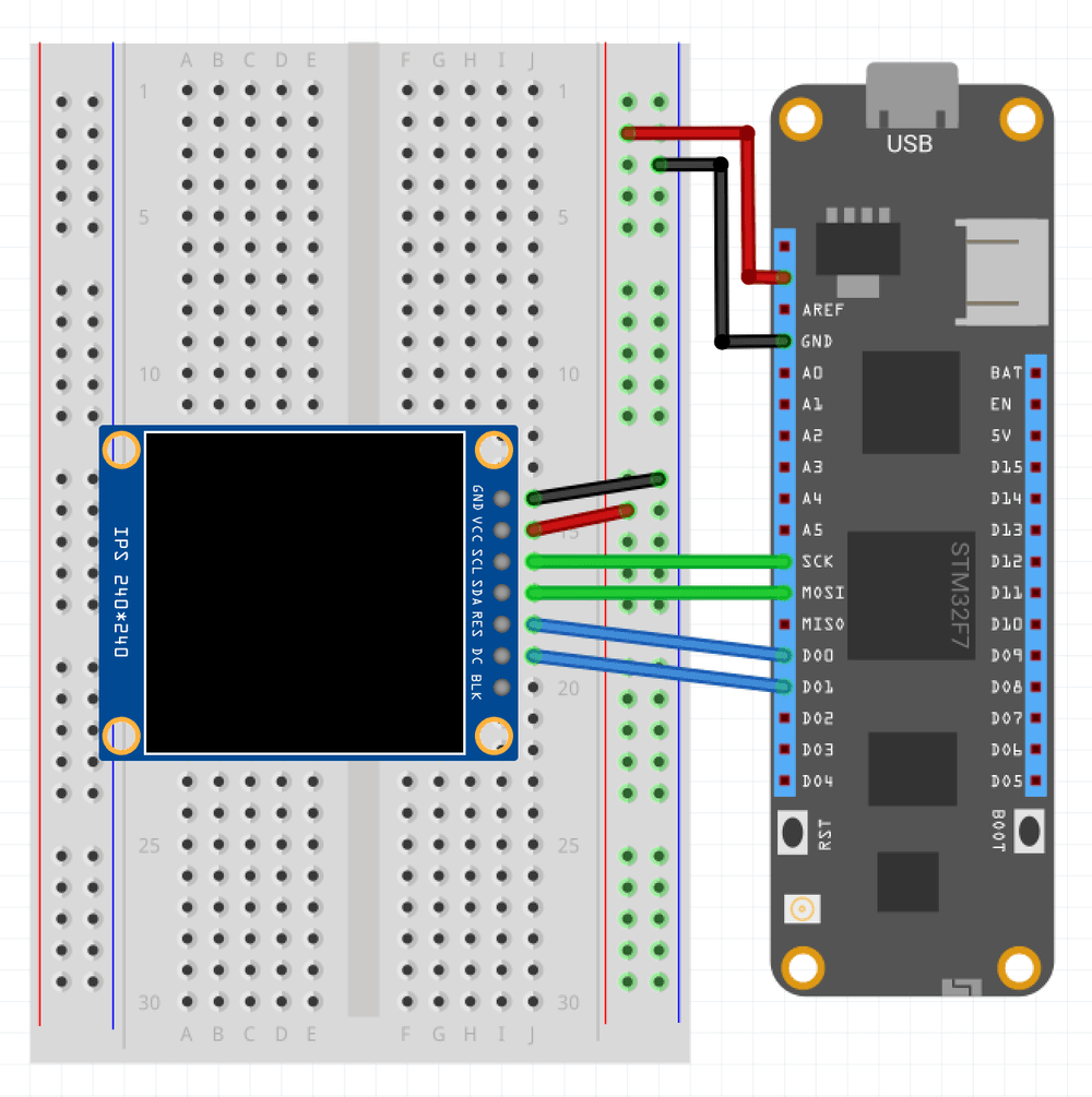
To wire a Gc9a01 to your Meadow board, connect the following:
| Gc9a01 | Meadow Pin |
|---|---|
| GND | GND |
| VCC | 3V3 |
| SCL | SCK |
| SDA | MOSI |
| CS | D02 |
| DC | D01 |
| RESET | D00 |
It should look like the following diagram: